Linear Circuit Analysis
1. Introduction
2. Basic Concepts
- Charge, current, and voltage
- Power and energy
- Linear circuits
- Linear components
- Nodes and loops
- Series and parallel
- R, L & C combinations
- V & I combinations
3. Simple Circuits
- Ohm's law
- Kirchhoff's current law
- Kirchhoff's voltage law
- Single loop circuits
- Single node-pair circuits
- Voltage division
- Current division
4. Nodal and Mesh Analysis (DC)
5. Additional Analysis Techniques (DC)
- Superposition
- Source transformation
- The $V_{test}/I_{test}$ method
- Norton equivalent
- Thévenin equivalent
- Max power transfer
- DC analysis of L & C
6. AC Analysis
7. Magnetically Coupled Circuits
8. Polyphase Systems
9. Operational Amplifiers
10. Laplace Transforms
11. Time-Dependent Circuits
- Introduction
- Inductors and capacitors
- First-order transients
- Second-order transients
-
Parallel RLC circuits
Series RLC circuits - Nodal analysis
- Mesh analysis
- Laplace transforms
- Additional techniques
12. Two-Port Networks
Appendix
Linear Components (Devices)
Table 1 shows a list of linear components (also called devices or elements) used in linear circuit analysis. All the components (and, implicitly, their current-voltage characteristics) are assumed to be ideal.
| Name/Unit | Symbol | Description |
|---|---|---|
| Resistor Ohms, $Ω$ |
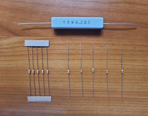
Resistors
|
A resistor is a 2-terminal device that satisfies Ohm's law:$$\begin{equation}V(t)=I(t)R\end{equation}$$ where $R$ is the resistance and $V(t)$ is the voltage from the terminal where current $I(t)$ is assumed to enter the resistor to the terminal where the current is assumed to exit the resistor. In the case of DC circuits (i.e. when the voltage and current do not depend on time) the above equation is usually written as $V=IR$, where $V$ and $I$ are the DC values of the voltage and current. In the case of AC circuits (in frequency domain) the Ohm's law can be written in the same way, but $V$ and $I$ are the complex values of the voltage and current.
Why do resistors warm up? When current flows through a resistor, the moving charge carriers (usually electrons) collide with the atoms of the resistive material. These collisions impede the flow of electrons and convert part of the electrical energy into random thermal motion of the atoms — i.e., heat and possibly into light. This process in which the electrical energy is converted into heat is called Joule heating (or resistive heating). |
|
Capacitor Farads, $F$ |
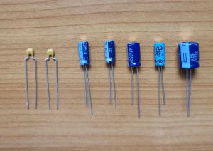
Ceramic and electrolytic capacitors
|
A capacitor is a 2-terminal device in which the current and voltage satisfy the following equation $$\begin{equation}I(t)=C\dfrac{dV(t)}{dt}\end{equation}$$ where $C$ is the capacitance (see the figure for notation). Can the voltage across a capacitor change instantaneously? The answer is no, because an instantaneous change in voltage would require an infinite current (I = C dV/dt). In practice, forcing a sudden change in voltage can cause very large currents or voltage spikes that may damage the capacitor or other circuit components. Always provide a proper discharge or protection path instead of abruptly changing the voltage. Capacitors can be divided into polarized and non-polarized types:
|
|
Inductor Henries, $H$ |
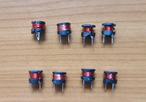
Inductors
|
An inductor is a 2-terminal device in which the current and voltage satisfy the following equation $$\begin{equation}V(t)=L\dfrac{dI(t)}{dt}\end{equation}$$ where $L$ is the inductance (see the figure for notation). Can the current through an inductor change instantaneously? The answer is no, because doing so would make the voltage across the inductor infinite (see the equation above). Therefore the current cannot change instantaneously. In practice, avoid sudden interruptions of current (for example, disconnecting the inductor abruptly), since forcing the current to drop rapidly can produce very large voltages that may damage the inductor or other components. |
| Impedance Ohms, $Ω$ |
An impedance is a 2-terminal device that is defined in the frequency domain (i.e. in AC circuits) and in which the complex current and complex voltage satisfy the following equation $$\begin{equation}V=Z I\end{equation}$$ where $Z$ is the (complex) impedance (see the figure for notation). Notice that the same symbol (rectangle) is sometimes used to represent a "black" box, which is an electronic component with two terminals that can contain combinations of resistors, inductors, capacitors, sources, etc. | |
|
Voltage source (independent) Volts, $V$ |
An independent voltage source is a 2-terminal device in which the voltage from the positive to the negative terminals is always equal to $V$. The current flowing through a voltage source is generally unknown until the circuit is solved analytically (or the current is measured experimentally). If a voltage source is short-circuited, the circuit presents almost zero resistance to the source. As a result, the current rises dramatically, often far exceeding the source’s rated output. In general, this should never be done, as the excessive current can damage the source unless it is equipped with an appropriate protection mechanism. |
|
|
Current source (independent) Amperes, $A$ |
An independent current source is a 2-terminal device in which the current flowing in the direction of the arrow is always equal to $I$. The voltage across a current source is generally unknown until the circuit is solved analytically (or the voltage is measured experimentally). Note that a current source adjusts the voltage across its terminals to maintain the current at its specified value. But what happens if a current source is disconnected from the circuit so that its terminals are left open? In practice, one should never do this, because with no path for current flow the source may develop an excessively high voltage and could be damaged unless it is equipped with a protection mechanism. |
|
| Dependent voltage source Volts, $V$ |
A dependent voltage source is a 2-terminal device in which the voltage from the positive to the negative terminals is equal to the value indicated ($V_x$ in this case), which can depend on other currents and voltages in the circuit. | |
| Dependent current source Amperes, $A$ |
A dependent current source is a 2-terminal device in which the current flowing in the direction of the arrow is equal to the value indicated ($I_x$ in this case), which can depend on other currents and voltages in the circuit. |
In addition to the linear components listed in Table 1, other examples of linear devices include transformers, operational amplifiers, and linear sensors. The first two of these components—transformers and operational amplifiers—will be studied in detail in later sections of this WebBook.
See also
-
Identify resistors, capacitors, inductors, current and voltage sources in electric networks
Circuit with resistors, capacitors, inductors and independent sources
Circuit with resistors, capacitors, inductors, dependent and independent sources